เครื่องวัดขนาดชิ้นงาน แบบ 3 มิติ
Coordinate measuring machine Model Promas 575 Micro
3D Coordinate Measurement Machine
(Type of Micro 575)

Configuration list
|
NO.
|
Item
|
Name
|
Specification
|
Maker
|
Set
|
|
1
|
Basic machine
|
|
Micro 575
|
NANO
|
1
|
|
2
|
Probe system
|
Probe head
|
MH20i manual indexing probe head
|
RENISHAW
|
1
|
|
Probe module
|
TP20-STD
|
RENISHAW
|
1
|
|
Stylus
|
As per the stylus kit
|
RENISHAW
|
1
|
|
Sphere base
|
Kit T5
|
|
1
|
|
Sphere
|
φ25
|
|
1
|
|
3
|
Controller
|
RENISHAW
|
UCC T3-2
|
RENISHAW
|
1
|
|
4
|
PC
|
Computer
|
3.3G/4G/500G
|
DELL
|
1
|
|
Printer
|
A4 Ink
|
HP
|
1
|
|
5
|
Software
|
Rational DMIS
|
External-Array
|
1
|
|
6
|
Technical material
|
Manual (Instruction of installation, operation, repair and maintenance)
|
|
1
|
|
7
|
Certificate
|
Factory quality certificate
|
|
1
|
|
8
|
Joint
|
φ10
|
|
1
|
|
Air cable
|
φ10
|
|
1.5m
|
|
9
|
Remarks
|
|
|
|
Description of the basic machine:
Micro is new-generated CNC CMMs with a mature and word-class technology under mass production at NANO. This machine has adopted precision slant girder technology (patented) designed by advanced F.E.M. (finite element method), which has the high precision, high performance and high steady characteristics. The machine’s perfect style, strong rigidity, lightweight and close frame movable bridge structure, which configured with the world famous high-quality specific 3D CMM control system, makes it become the highly appreciated product by comparing with its competitive price and high practical quality. It will meet customer’s challenging demand with a comprehensive measurement solution.
Introduction of Basic Machine:
- Model Name: Micro 575CMM
- Measuring range: 500 mm × 700 mm × 500 mm
- Max part weight:1000kg
Commercial Terms:
- Offer Validity Period: The offer is valid within 30 days once it is given.
- FOB both agreed port in China: USD /set
- Delivery: within 30 days once the advance payment is received.
- Payment term: 30% by T/T in advance, 70% by T/T in advance before shipment.
- Package:Wooden case
Technical Description
1. Basic Machine:
- Adoption of advanced F.E.M. (finite element method) makes it have a strong rigidity, small geometry error, high precision, high performance and high stability.
- The mechanical overall structure adopts strong rigidity, light weight and close frame movable bridge structure, which is simple, compact and has strong loaded capacity and good moving performance.
- Granite fixed worktable ensures strong heavy load, expanse and simplicity for loading and unloading.
- Y-axis guide-way adopts dove tail type, which has high precision and good stability.
- Three axes' adoption of quality granite guarantees small coefficient in thermal expansion and uniform temperature specialty so that it serves to excellent stability in temperature, good anti-transmogrification, strong rigidity and small geometrical error in motion.
- Three axes' adoption of quiescent air pressure air-bearing guide way, comprised of air bearings which are self-cleaning, pre-loading and high precision, guarantees the large span of bearings, strong anti-sways, small resistance, no abrasion and stable motion.
- Adoption of world famous reflecting metal tape measuring scale system, which has a close thermal expansion coefficient with most work piece and assure a good repeatability.
- Drive system adopts world famous high performance DC servo drive system and dentiform tape gearing, which guarantee the drive’s fastness, precision and perfect movement.
- Z-axis adopts cylinder equilibrator system, which improves orientation precision and stability greatly for Z axis.
- The control system adopts well-known exclusive Europe internationally advanced up-down dual computers control system, which improves the system’s reliability and anti-jamming capacity greatly.
2. Technical Index:
01. Probe System:
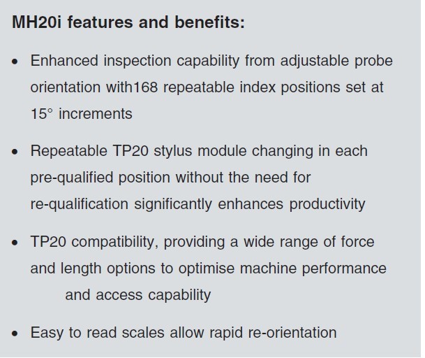
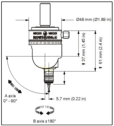
- RENISHAW MH20I motorized indexing probe head with integral TP20 module mount
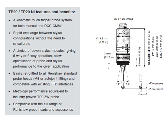
Specification Probe

TP20/TP20 NI
|
Order NO.
|
Name
|
Ball material
|
Length
(mm)
|
Ball Dia.
(mm)
|
Piece
|
|
A-5000-7806
|
Straight Stylus
|
Ruby
|
10
|
1
|
1
|
|
A-5000-7807
|
Straight Stylus
|
Ruby
|
10
|
2
|
4
|
|
A-5000-4160
|
Straight Stylus
|
Ruby
|
20
|
3
|
1
|
|
A-5000-4161
|
Straight Stylus
|
Ruby
|
20
|
4
|
1
|
|
M5000-3648
|
Extension
|
Stainless steel
|
20
|
|
1
|
|
M5000-4162
|
Extension
|
Stainless steel
|
30
|
|
1
|
|
A-5000-3627
|
Center base
|
Stainless steel
|
|
|
1
|
03、Datum tool:
A datum ball (Φ25) and datum ball stand 1 set
04、Performance Data:
Linear scale: RENISHAW grating rulers from Britain
Resolution of the RENISHAW reading head: 0.5mm
Measuring Range: 500mm×700mm×500mm
MPEe: E≤1.8+3.3L/1000mm
MPEp: R≤1.8mm
3.Environment Requirement
- Temperature: 20+2℃ 1℃/h 1℃/m 2℃/24h
- Humidity: 40%-70%
- Power Supply: 220V+10%, 50HZ-60HZ
- Air Supply: ≥0.55Mpa
 |
 |
| |
|

4.Controller:RENISHAW UCC
- Adoption of the principle that the control layer get isolated from the application layer for CNC of the coordinate measuring machine provides a firm basis for high accuracy measurement, high efficiency and stability for the machine.
- The DC servo motor of the drive system is vibrationless. It works at the speed of curve T or S.
- Configuration of 3 axis close loop working method enables input of three road TLL quadrature pulse and realization of vector control.
- The probe interface is compatible with many type touch-trigger probes, analog scanning probes or non-contact scanning probes. It supports different mode probes of many companies.
- The controller is more safe and reliable. It covers many control modes, so that, when an accident which can lead machine to halt occurs, the controller can switch to the corresponding mode to stop the machine. Don’t worry about the occurrence of “over speed” accident. And it will be diagnosed out online if there is some trouble with the machine.
- RENISHAW UCC control system can realize TP SCAN function. It can trace the curve or curved surface, scanning and measuring. Therefore, the machine without a laser scanner or a contact scanning probe, can complete the product scanning. And it is easy to measure the curved surface in the reverse engineering application.
- The probe can move smoothly on a straight path or a circular curve faster and more efficiently. In this case, It’s possible to scan and measure a round part.
- The control system is stable and reliable. Its maintenance is also easy. Problem diagnosis and settlement is easy and clear because the control layer is isolated from the application layer and it’s impossible for a problem on one layer to affect the other layer.
- Human-oriented design for the hand controller. The hand controller provides keys and a joystick for the user. The keys and the joystick are easy and reasonable for users to control the machine.
5、Software system :Rational DMIS
The powerful functional software system of Open DMIS has a full graphical display, so it is visualized, convenient and intelligent.
Functions
- The software rightly configures the machine movement parameters and environmental ones.
- The measuring software package has an English version. Except operation interface, the part program and output reports are in English, moreover, the language is available to be switched to another certain language. You can get online help if necessary. The operation brochure and the training material are provided to users.
- The software has the function of probe system configuration and adjustment. The probe’s control and its diameter’s preference is set by the software. The stylus is adjusted automatically, the result’s judgment method is also supplied by the software, which is quite simple and speedy. An automatic adjustment program is then created to adjust a certain probe alone.
- The software can built a measuring-coordinate system with a certain basic measured element group.
- Except the basic 3-2-1 part-position finding function, the measuring software package also can be used to find the exact position of a part especially with free-form surfaces, in the iterative method or the best match way.
- The user can build a measuring-coordinate system with the basic elementary group and part of its vectors by the best fit method.
- The name and the direction of the measuring-coordinate system can be adjusted according to users’ needs.
- The measuring-coordinate system can be translated and rotated according to users’ needs.
- A measuring-coordinate system can be built with structural elements.
- The user can get measuring points by the software.
- Such basic geometric elements’ measurement as points(planar points and spatial points), lines, planes, circles, ellipses, rectangles, circular cones, cylinders, circular rings and balls. It can be finished automatically for right parts under the measuring program.
- Some motions can be finished by the software, such as the element’s structuring, switching, representation, projection, storage, calling and some other related computing.
- The user can build the coordinate system or the work-piece coordinate system with the software. The two kind of coordinate systems also can be stored, called or switched.
- Dimensional tolerance evaluation, geometric tolerance evaluation.
- The file of measurement results may be stored or input through the software.
- Under the graphics drive, fast programming is realized. So that the object is finally measured.
- The software has the function of digital-analog theoretical element automatic recognition. then the measuring program is fast created.
- The point is probed as soon as the stylus touches it. In this way, the measurement efficiency is improved.
- The software can computing and switch a certain geometric element group into some another geometric element. For example, it can make a circle out of many points, or make a surface.
- The software can calculate the relation between or among geometric elements, such as distance, intersection, projection, and angularity, etc.
- The software can calculate such geometric errors as linearity, flatness, roundness, cylindricity, parallelism, verticality, symmetry, concentricity, coaxiality, section run-out, radial run-out and total run-out, etc.
- The software can differently color and mark the error which surpassed the set value.
- The excellent human machine interface is easy to operate. And the operation software interface is displayed in English.
- The software can self-calculate and generate a program automatically. Then the software also can simulate to run measuring program.
- The pure DMIS kernel is 100 percent up to the DMIS standard.
- Some usual DMIS sentences, functions and macros are embedded.
- The software can self-calculate to create standard DMIS sentences.
- Manual mode: the user can operate the control stick to measure something.
- The self-calculation and memory mode: after the mode, the manual measurement process can be remembered and finally becomes part of the program.
- Repeat mode: this mode can call part of the program to measure something.
- Editing mode: this program can add points to measure and can modifier part of the program.
- 100 percent graphic demonstration. The measuring software package should has the graphic demonstration function, namely, all the measurement and calculation elements can be graphically displayed and operated.
- The machine model is graphically built, so are these operation such as probe building, calibration, measurement, structure, tolerances and outputting. Such functions as graphically displaying, path simulation, collision test and measurement plan can improve measurement’s operability and predictability. This will make the operation safer and reduce the hardware getting broken risk, maybe due to wrong operation or unskilled operation.
- Various graphical output reports.
- Offline measuring simulation, interference detection.
- The measuring software package is applied to reverse engineering, and outputs something in IGES format. It makes 3-D graph out of some certain basic elements, then uploads this graph to computer-aided design system software, such as UG, PROE. In this case, the unknown part is measured and drawn, then the mathematical model is uploaded to the design software to be processed.
- The data can be stored, then switched and edited in EXCEL software. It is printed directly or printed according to the user-required form.
- The data, gotten through 3-D coordinate measurement, may be switched into the report mode. Then the user also can edit the report.
- Data output: LCD, printer.
C. Service terms
1. After-sales service
NANO will support the after-sales service issue for this machine。
2. Installation and Acceptance:
01. (Confirmation of Environmental Requirement):
The installation will be carried out after Buyer’s self-test approval and confirmation according to Technical Requirement for Installation Environment and Application.
02. Installation and Adjustment at Customer’s Site:
System installation, including start-up, assembles and metrology test will be carried out by the service engineer of NANO Metrology. The concerned environment and facilities for the CMM installation must conform to the requirement of the standard specifications before the installation.
03. Acceptance Method:
The acceptance method is based on the ISO10360-2 to execute inspection and acceptance.
04. Testing Items:
Exterior appearance and the interaction between all the parts.
Function of Computer, printer and software
- MPEp
- MPEe
06. Testing Method:
The machine should be on power more than 24 hours before test.
Visual observation and operation experiment are applied to test exterior appearance and the mutual interaction between all the parts.
Corresponding diagnostic testing procedures are applied to test the functions of computer, printer and software.
- Test for MPEp :
On the calibration sphere of 25mm diameter, probe system randomly picks up 25 points in the direction of arbitrary location with the length of 20mm stylus. Each picked point on the hemisphere tries to spread evenly. The minimal quadrate center is calculated by all 25 measured values, meanwhile to calculate radial distance of points in which the largest radial distance subtracting the minimum radial distances equals probing error. The result should meet the given P value.
- Test for MPEe:
Seven positions are freely selected in the working space of coordinate measuring machine. Five measurers with different size are measured in each position and each measurer is measured three times. The total measuring times is 105 times in 35 groups of measuring length.105 error values △L are calculated (converted into um), if no one goes beyond the limit of the E, this test of E is passed
Within 35 Groups of measuring length, allowed a maximum of five groups in which one time going beyond the E in the three repeated measurements. For each measuring length that goes beyond the limit of E, the corresponding position should be measured 10 times. If all the length measurements error of the △L, gained by 10-time repeated measurement, are within E value, the value of their error (E) test are passed.
07. Acceptance and handover:
Both sides follow the procedures of handover and acceptance based on test report, packing list and contract.
If acceptance is in conformity with the requirement, the representatives of the both sides sign in the acceptance report. If objection, both sides should resort to negotiation for bilateral agreement. Remained problems may be recorded in the memorandum for further service and settlement.
4、Promise:
01、Quality:
During the warranty period, if the equipment fails to be confirmed as a quality problem, our company promises to carry out the maintenance free of charge
02、Service:
If we receive a service call from the user, we will respond within 8 hours.

 เครื่องวัดขนาดชิ้นงาน แบบ 3 มิติ Coordinate measuring machine Model Promas 564 MANUAL
  เครื่องวัดขนาดชิ้นงาน แบบ 3 มิติ Coordinate measuring machine RPS model EVO-Series
  เครื่องวัดขนาดชิ้นงาน แบบ 3 มิติ Coordinate measuring machine Model Meti8106 Semi Automatic
  เครื่องวัดขนาดชิ้นงาน แบบ 3 มิติ Coordinate measuring machine Model Metic 565
  เครื่องวัดขนาดชิ้นงาน แบบ 3 มิติ coordinate measuring machine model VMC 3222
  เครื่องวัดขนาดชิ้นงาน แบบ 3 มิติ coordinate measuring machine model VMC 6600M VMC 6606M VMC 6646M VMC 6666M
  เครื่องวัดขนาดชิ้นงาน แบบ 3 มิติ coordinate measuring machine model VMC 5500 VMC 5546M VMC 5506M VMC 5566M VMC 5506L
  เครื่องวัดขนาดชิ้นงาน แบบ 3 มิติ coordinate measuring machine model Special Multifunctional CMM
  เครื่องวัดขนาดชิ้นงาน แบบ 3 มิติ coordinate measuring machine model Summary Series Gantry CMM
  เครื่องวัดขนาดชิ้นงาน แบบ 3 มิติ coordinate measuring machine model Royal Series Bridge Type CMM ROYAL 10128 ROYAL 121510 ROYAL 152012
  เครื่องวัดขนาดชิ้นงาน แบบ 3 มิติ coordinate measuring machine model Micro Series Bridge Type
  เครื่องวัดขนาดชิ้นงาน แบบ 3 มิติ coordinate measuring machine model EM Series
  เครื่องวัดขนาดชิ้นงาน แบบ 3 มิติ coordinate measuring machine model High Precision Magi Series
  เครื่องวัดขนาดชิ้นงาน แบบ 3 มิติ coordinate measuring machine model BACES 3D
